

Deploying industrial robotics automation requires far more than bolting an arm to the floor and running a pre-written routine. You have to balance payload inertia and shield signal lines from electrical noise when high-voltage drives kick on. It takes work.
This guide gives you the structural and control frameworks needed to build operational automated cells. It will cost you focused effort: you must map PLC network registers and work through mechanical payload calculations. Expect precise engineering requirements instead of high-level commentary.
Whether you are automating a factory floor or building a Final Year Project, the integration principles stay identical. Respect the hardware limits first. Software logic works only when physical components hold tight.
What Is Industrial Robotics Automation?
Industrial robotics automation is the precise convergence of programmable mechanical manipulators, sensor arrays, and real-time control algorithms. You replace variable manual assembly with high-speed electro-mechanical execution. Precision demands closed-loop feedback. High-resolution encoders feed axis position data directly to the controller, while PLC control buses transmit sensor signals with deterministic microsecond timing. Meanwhile, inverse kinematics solvers compute complex matrix transformations, turning tool spatial coordinates into individual joint motor commands. Integrating robotics in modern manufacturing processes allows your facility to pivot from fixed manual stations to flexible, software-driven production.
Evaluating Automation Categories
Choosing the correct framework depends on your payload, batch volume, and part variance:
- Hard Automation: Relies on dedicated mechanical cams, pneumatics, and fixed indexing tables. It yields high speed for one single part. Changing product specs requires mechanical rebuilds.
- Flexible Robotic Automation: Uses multi-axis articulated arms or SCARA hardware. You alter motion profiles and tool routines through software, eliminating physical teardowns between different product runs.
- Collaborative Systems: Uses force-torque sensors and motor current monitoring to detect resistance. These units operate beside human operators without requiring perimeter safety fencing.
Moving a plant from manual processing to synchronized robotic cells requires linking manipulators, conveyors, and safety interlocks into unified controller networks. When vision sensors register incoming workpieces, kinematics solvers compute trajectory vectors in real time. Tooling aligns instantly. The cell executes coordinated material handling, joining, and inspection tasks without human intervention.
Architectures of Industrial Manipulators: Articulated, SCARA, Delta, and Cartesian
Choosing mechanical structures drives your physical cell geometry. Kinematic design governs how joint movements transform into end-effector positions. Degrees of freedom (DOF) determine spatial flexibility. Payload capacity defines maximum load at peak tool extension, while the reach envelope specifies your active 3D volume.
Matching Mechanical Architectures
Evaluating articulated and SCARA manipulator designs alongside Delta and Cartesian options requires mapping task constraints directly to joint mechanics. Articulated arms feature five or six rotary joints, mimicking a human arm to reach around obstructions during heavy arc welding or spray application. SCARA arms use parallel rotary axes for high-speed lateral motion with rigid Z-axis stability. That setup fits flat-plane insertion and electronics assembly. Delta arms use lightweight parallel links suspended overhead to pick small parts rapidly without using floor space. Cartesian gantries trade rotational versatility for linear stiffness, providing steady accuracy over wide rectangular grids.
| Architecture | Degrees of Freedom | Typical Payload | Primary Kinematic Strength |
|---|---|---|---|
| Articulated | 5 to 6 | 3 kg to 2,300 kg | Spherical work envelope and wrist orientation |
| SCARA | 3 to 4 | 1 kg to 50 kg | Z-axis rigidity with rapid lateral movement |
| Delta | 3 to 4 | 0.5 kg to 12 kg | Overhead picking with high acceleration |
| Cartesian | 3 linear | 5 kg to 1,000 kg | Uniform precision across linear footprints |
Selecting incorrect mechanical geometry forces expensive workcell redesigns. If your industrial robotics automation project demands arbitrary end-effector orientation in 3D space, specify articulated arms. For rigid, high-speed top-down assembly, choose SCARA arms or Cartesian gantries instead. Always match the reach envelope directly to your workspace floor footprint early.
Designing and Building Custom Robotic Workcells
Simulation and Payload Sizing
Workcell development starts inside simulation environments like RoboDK or Siemens Process Simulate. Import 3D CAD models of your robot manipulator and custom end-effector tooling. Define your tool center point (TCP) offset values ($X, Y, Z, A, B, C$) from the robot tool flange face. Run cycle time simulations by plotting move trajectories and checking joint speed profiles against cycle targets. Calculate total end-effector mass and center of mass distance. Input these exact payload inertia specs into your robot controller menu. Correct inertia parameters prevent arm jitter and avoid gear train wear during rapid acceleration phases.
Mounting rigidity dictates path repeatability. Bolt your steel base plates directly to concrete floors using chemical anchor studs. Base plate flex under high deceleration causes severe position drift. Cable harness dress packs demand careful routing. Tight bend radii rupture internal copper conductors under cyclic twisting. Route dynamic pneumatic lines and sensor cables through flexible energy chains attached at joints 3 and 4 to eliminate strain.
Physical Assembly and Zero-Point Alignment
Physical installation follows a tight sequence over two days. Mount your manipulator and connect remote fieldbus I/O modules. When executing your industrial robotics automation projects, calibrate the physical TCP using a four-point touch-off sequence against a fixed reference needle. Jog your robot to touch the needle tip from four distinct orientation angles. The robot controller calculates the active tool frame matrix from these inputs. Relying on specialized custom robotics integration services streamlines mechanical alignment and ensures accurate cell setup prior to main commissioning.
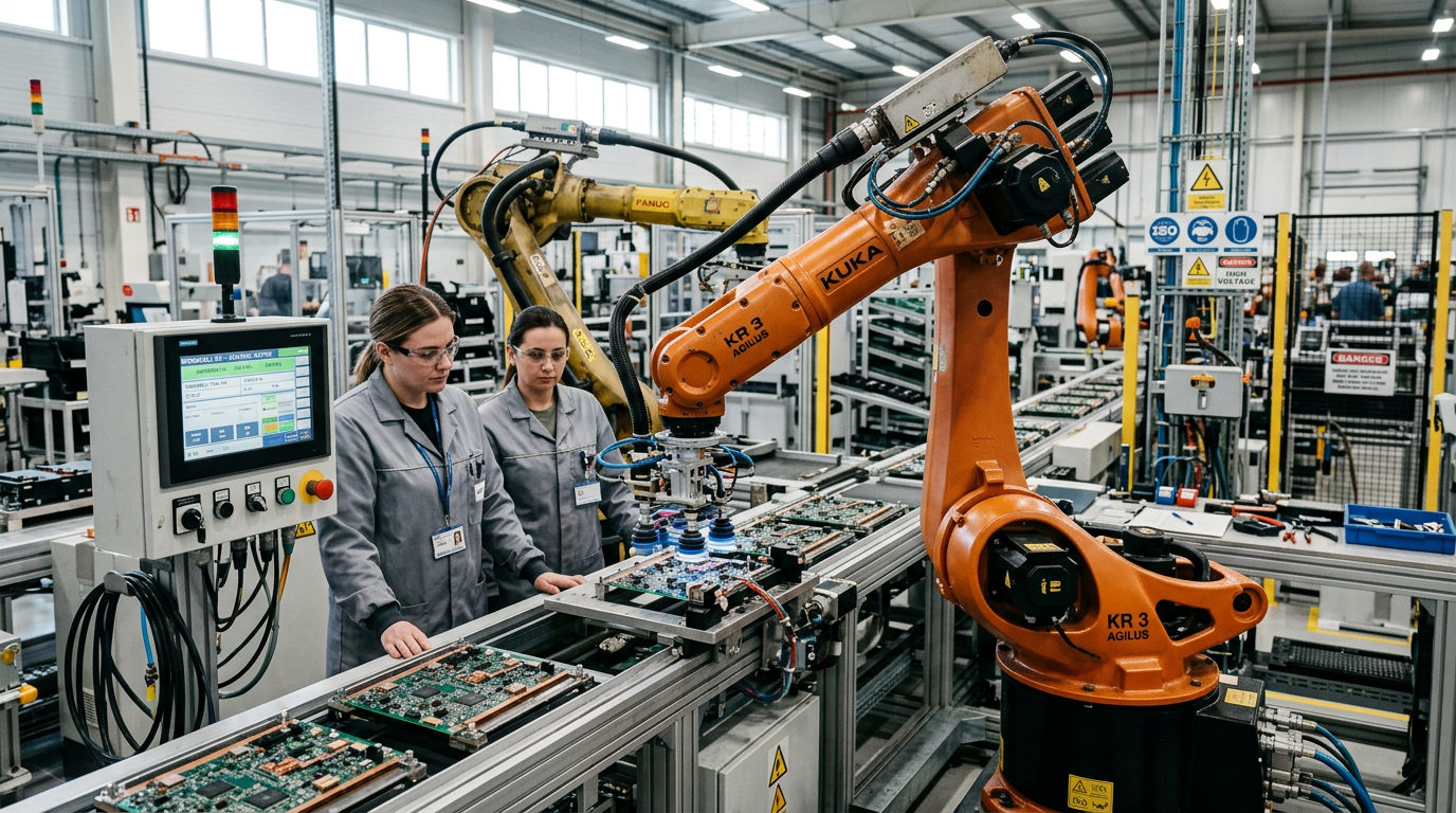
Programming and AI Vision Integration for Autonomous Systems
ROS2 Trajectory Nodes and Vision Offset Tuning
You write custom ROS2 nodes in Python using rclpy to coordinate dynamic motion planning. Your node subscribes to camera point clouds and publishes execution trajectories to joint trajectory controllers. When pairing a 3D stereo camera with a 6-axis arm, run eye-in-hand calibration to calculate sensor transformation matrices. Convert bounding box centroids into robot base-frame offsets using tf2_ros transform trees. Then, send dynamic X, Y, Z, and yaw offset vectors to your teach pendant script over TCP/IP sockets. This setup keeps industrial robotics automation resilient against unoriented parts. Data stays clean.
Building these complete hardware-software stacks requires reviewing details about smb robotics engineering to structure system interfaces effectively.
Lighting Constraints and Live Teach Calibration
Shift changes bring harsh light variations that break vision models. Sun glare once dropped object classification confidence from 0.94 down to 0.35 on a sorting cell. Fix this edge case by routing raw RGB frames through an HSV saturation filter combined with thresholding prior to tensor conversion. Removing specularity keeps model accuracy above 0.89 across all lighting cycles.
Offline programming in tools like RoboDK speeds up layout design. But physical mounting surfaces deviate from digital twins. Relying purely on CAD paths creates severe collision risks. Use offline software to generate baseline trajectories, but finish with live teach-mode calibration using the pendant on the factory floor. Live touch-ups take forty minutes. It saves your end-effector from catastrophic crashes.
Global Deployment Benchmarks and Industry Statistics
Regional Density and Federation Deployment Trends
When evaluating industrial robotics automation for your facility, baseline density metrics provide clear target reference points. The International Federation of Robotics tracks robot density per 10,000 employees across major industrial regions globally. Automotive manufacturing continues to maintain the highest robot density, relying heavily on automated spot welding, painting, and heavy material transfer. Electronics manufacturing follows closely, driven by high-volume surface-mount assembly and precise component handling.
Data published by the International Federation of Robotics shows Asian manufacturing hubs leading overall deployment volume. South Korea, China, and Japan maintain high annual installation rates. European industrial centers like Germany sustain strong density figures within automotive lines, while North American facilities show steady adoption growth across general manufacturing segments. Reviewing global industrial robot installation statistics allows you to benchmark your operational strategy against international peers.
High-Growth Applications
Heavy automotive manufacturing no longer monopolizes automated production equipment. Semiconductor fabrication plants demand specialized, cleanroom-rated articulated arms to transfer sensitive silicon wafers without particulate contamination. Similarly, battery assembly operations for electric vehicles require high-payload manipulation combined with exact cell-stacking tolerances. Strict cleanroom standards and thermal pack assembly make rigid automation mandatory.
Logistics automation represents another rapidly expanding sector. Warehouses, sorting facilities, and distribution centers integrate autonomous mobile units alongside stationary manipulators to accelerate order picking and palletizing. Evaluate these cross-industry benchmarks carefully. You need real baseline data to justify your hardware architecture and cycle-time targets.

The Big Four Manufacturers and Industrial Integration Ecosystems
Comparing the Big Four Ecosystems
Four vendors dominate industrial robotics automation deployments across assembly lines and machining cells: FANUC, ABB, Yaskawa Motoman, and KUKA. Selecting between them depends on software architecture, path accuracy requirements, and native controller integration.
| Manufacturer | Native Language | Ecosystem Characteristics |
|---|---|---|
| FANUC | KAREL / TP | High mean time between failures, widespread automotive footprint. |
| ABB | RAPID | Precise path tracking, modular abb robotic systems and software options. |
| Yaskawa Motoman | INFORM | Multi-robot control from one cabinet, arc welding specialty. |
| KUKA | KRL | Windows-based controller platform, real-time motion modifications. |
FANUC uses proprietary teach pendant programming alongside KAREL for low-level execution. It is dependable. But debugging syntax errors requires specialized software training. ABB relies on RAPID, a structured language that makes complex spatial calculations straightforward. Yaskawa uses INFORM for efficient teaching routines, while KUKA runs KRL on a PC-based control architecture that simplifies third-party sensor integration.
Selection Criteria and Network Protocols
Base your vendor hardware decisions on two core practical factors:
- Spare parts availability: Local distributor stock dictates whether a broken joint motor halts production for four hours or four days.
- Native controller interfaces: Integrated network cards must match your plant standard to avoid expensive protocol converters.
Interoperability hinges on deterministic data exchange. Industrial Ethernet protocols like EtherNet/IP, PROFINET, and EtherCAT handle real-time kinematic control between the master PLC and the manipulator cabinet. For supervisory monitoring, standardizing on OPC UA ensures vendor-neutral data streaming without rewriting base controller programs.
Integrating Motion Control and Industrial PLC Networks
Configuring Real-Time Fieldbus Handshakes
Deterministic networks connect your programmable logic controller (PLC) directly to the robot motion controller. When mapping I/O over EtherCAT or PROFINET IRT, set your cyclic communication task to a fixed update rate of 2 ms. Map system interlock signals to explicit byte offsets in memory. Assign byte DB10.DBB0 for standard handshakes: bit 0 signals “PLC Ready,” bit 1 flags “Workpiece Clamped,” and bit 2 confirms “Robot Axis Cleared.” Modern integrated motion control technology platforms rely on these tight clock cycles to prevent path deviation during continuous pathing.
Safety Loops and Eliminating Timing Jitter
Emergency stop loops require hardware dual-channel cross-checking inside dedicated safety tasks. Assign physical input bits I0.0 and I0.1 to your dual-channel E-stop chain, writing directly to safety register Safety_DB.X0.0 for the main drive enable. Handshake signals must execute in sequence. If the robot controller clears its handshake bit before the PLC acknowledges receipt, motion halts instantly. A missing millisecond breaks the cycle.
Micro-stoppages on assembly lines usually come down to network jitter or loose shielding. When diagnosing intermittent halts in your industrial robotics automation deployment, open your fieldbus diagnostic tool to monitor frame latency and dropped packets. Swap standard patch cables for double-shielded M12 industrial Ethernet assemblies. Ground all cable shields directly at the enclosure entry point to sink high-frequency noise generated by nearby servo drives. Finally, adjust your communication watchdog timer to trigger a fault after 3 consecutive dropped packets rather than letting axis synchronization drift.
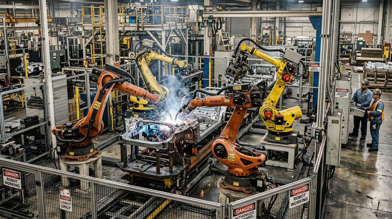
Financial Realities: Capital Costs, System Integration, and ROI
Hidden Integration Costs Beyond the Arm
Buying a robot arm is only your starting point. The bare arm usually accounts for less than a third of your project outlay. System integration costs 2x to 3x the base price of the robot hardware itself. That multiplier surprises first-time buyers. You must fund custom end-of-arm tooling, safety fencing, interlocked access gates, dedicated electrical drops, and recurring software licensing fees.
Never bypass formal safety risk assessments. Skipping them creates site hazards and triggers expensive delays when safety audits pause your production line. Generating reliable robotic deployment budget estimates requires accounting for every sensor mount, cable carrier, pneumatic valve manifold, and controller enclosure before signing a vendor contract.
Calculating ROI and Identifying Unfeasible Cells
Before writing a capital request, evaluate your project economics with a clear payback formula:
Payback Period (Years) = Total Capital Investment / ((Annual Labor Offset + Annual Scrap Reduction) – Annual Preventative Maintenance Costs)
Preventative maintenance costs must include joint grease flushes, dress-pack cable replacements, safety scanner cleanings, and sensor recalibrations. If your calculated payback period stretches past the expected lifecycle of the target assembly, do not move forward with the build.
Industrial robotics automation is financially unfeasible for low-volume, high-mix job shops. When operators change fixtures and part geometries twice a day, constant retooling and trajectory programming consume your profit margin. Manual labor or basic modular fixtures deliver far better returns when part runs remain small. Know your limits before committing capital.
Career Specializations and Salaries in the Robotics Sector
Core Specializations and Industry Compensation
Engineering roles in industrial robotics automation fall into four main tracks. Controls Engineers program programmable logic controllers (PLCs), wire physical safety relays, and tune servo drives. Robotics Software Engineers build path-planning algorithms, perception pipelines, and C++ application packages. Systems Integrators physically assemble hardware, wire control cabinets, and commission robot cells on factory floors. Solutions Architects design complete plant automation layouts and balance system throughput targets. Compensation trends summarized across industrial robotics news and technical reports show that software architects and senior controls leads command the highest compensation bands due to the technical risks associated with live facility downtime.
Controls engineers start with high base salaries because field deployments carry high risk. Software engineers reach higher compensation ceilings as facilities deploy centralized fleet management and edge AI node arrays.
Transitioning from Academic FYPs to Engineering Leadership
Moving from a university Final Year Project (FYP) to commercial deployment requires dropping sandbox tools. You need hard skills. ROS scripts running on desktop Linux will not survive on a plant floor. You must write low-latency C++, configure real-time operating system (RTOS) kernels, and troubleshoot deterministic fieldbus networks like EtherCAT and PROFINET. Industry leadership requires mastering emerging technical domains. Senior engineers must direct AI perception integration for unstructured bin-picking and coordinate autonomous mobile robot (AMR) fleet management engines across warehouse management systems. Build complete hardware-to-software mastery to lead integration projects.
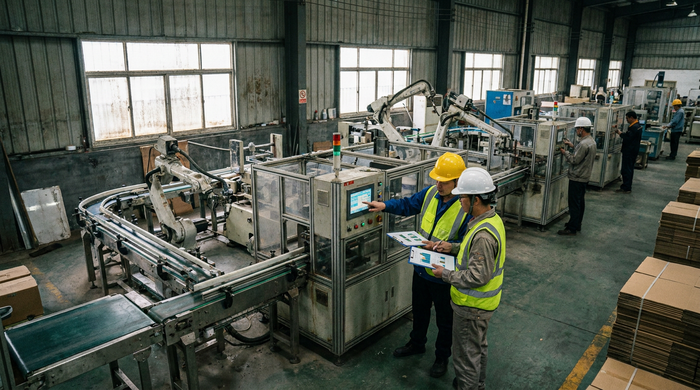
Operational Risks, Safety Standards, and Common Deployment Pitfalls
Compliance and Mechanical Failure Modes
You must design your cell around ISO 10218-1 for industrial arms and ISO 10218-2 for system integration. When operators share a workspace with manipulators, ISO/TS 15066 dictates force and speed limits to prevent crushing injuries. Ignore these standards and your workcell will fail safety audits, forcing costly floor redesigns.
Hardware wears down under heavy cycle loads. Encoder drift silently shifts your tool center point without triggering controller alarms. Gearbox backlash compounds positioning errors when accelerating maximum payloads. Dynamic flex fatigue snaps internal conductors inside cable tracks, while ambient lighting variations cause optical sensor blinding mid-cycle. You need structured diagnostic routines to catch these issues before severe crashes occur.
Handling Limits and Sensor Verification
Recognize where industrial robotics automation reaches its technical limit. Non-rigid material handling remains a high-risk deployment pitfall. Deformable items like rubber gaskets and loose wire harnesses warp unpredictably under friction. Standard 2D vision software loses part registration, and suction cups lose seal pressure on sagging geometry. If parts lack structural rigidity, custom automation is often a bad investment.
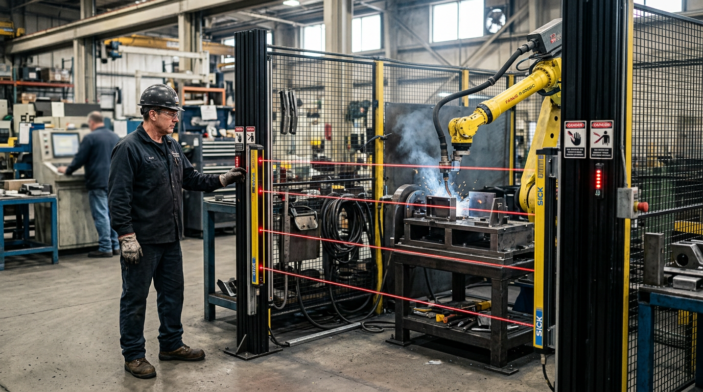
Perform manual validation before final commissioning sign-off. Test safety light curtains by interrupting optical paths at varied heights using calibrated test rods to verify immediate emergency stops. Step across every individual zone of safety pressure mats to confirm the main safety relay drops motor power before a person reaches a pinch point. Software status LEDs are not proof of compliance. Do not accept sign-off until you witness physical relay isolation during a simulated breach.
End-to-End Execution Checklist for Industrial Facilities and Engineering Projects
Phase-by-Phase Execution Sequence
Deploying industrial robotics automation demands disciplined execution. Skipping steps creates downtime later.
- Feasibility: Define payload limits, gripper mass, and target cycle speeds.
- Workcell Simulation: Model kinematics, collision paths, and reachability limits inside virtual tools.
- Hardware Selection: Specify robot manipulators, end-of-arm tooling, safety light curtains, and vision systems.
- Integration: Wire control panels, mount hardware, and establish fieldbus communication with the main PLC.
- FAT/SAT Testing: Validate system logic during Factory Acceptance Testing before conducting final Site Acceptance Testing on the plant floor.
Production Thresholds and Handover Documentation
Do not transfer a workcell from testing to live production based on assumptions. Force the system to hit clear performance gates first. Demand an uninterrupted 24-hour burn-in run with zero emergency stop trip faults. Confirm that cycle times stay repeatable within ±0.2 seconds of target across 500 consecutive operational loops.
Complete project sign-off requires three documentation packages:
- As-built EPLAN electrical schematics and pneumatic layout diagrams.
- Annotated software backup files for both robot controller programs and safety PLC logic.
- Final ISO 10218-1 and ISO 13849-1 safety audit verification reports.
Once live, validate post-commissioning KPIs by tracking overall equipment effectiveness against your original simulation baseline. Measure cell availability, mean time between failures, and scrap rates during week one. If your industrial build stalls or you need assistance with an advanced academic project, contact our automation engineering team to review your system architecture.
Isolate your single slowest manual task before buying hardware or writing control code. Map every micro-step and time the process with a stopwatch across twenty consecutive runs. You know this step worked when you hold an undisputed baseline cycle time and a standard deviation measured in seconds, not an optimistic guess. That precise timing dictates your motor sizing, vision system specs, and state machine logic.
Automation will not fix a broken manual process. If your mechanical tolerances drift, your part feeding jams continuously, or your project scope lacks clear state transitions, adding a high-speed arm only speeds up your errors. Systems integrators and engineering students looking for a quick solution without tuning sensor feedback or handling physical edge cases should not bother. Hardware is unforgiving. Secure your physical inputs, validate your baseline data, and build your automated system step by step.
Frequently Asked Questions
What is industrial robotics and automation?
Industrial robotics and automation involves using programmable robotic systems, artificial intelligence, and software to execute repetitive, hazardous, or high-precision manufacturing tasks automatically. By integrating custom hardware with advanced IoT sensors, you streamline production lines, reduce operational error, and increase throughput. This combination allows your facility to transition from manual labor dependency to a scalable, automated workflow.
Who are the big 4 in the industrial robotics industry?
The big four companies dominating the industrial robotics sector are ABB, FANUC, Yaskawa Electric, and KUKA. These manufacturers produce the primary articulated arms and motion controllers that power global manufacturing infrastructure. When designing your automated workcell, you will typically integrate software, sensors, and end-effectors around one of these four core hardware platforms to achieve seamless factory automation.
What does automated industrial robotics do?
Automated industrial robotics performs physical manufacturing tasks like welding, assembly, material handling, pick-and-place, and inspection without continuous human intervention. By combining robotic arms with tailored software and AI algorithms, these systems consistently execute complex movements at high speeds. You can deploy them to eliminate bottlenecks, maintain precise quality standards, and protect your workforce from dangerous operational environments.
What is the highest paid job in robotics?
Robotics Software Engineers and AI/Machine Learning Systems Architects consistently command the highest compensation packages in the robotics industry. These specialists design the core navigation, vision algorithms, and autonomous control logic that transform basic hardware into intelligent systems. If you specialize in integrating complex artificial intelligence with real-time software automation, your expertise directly drives the value of high-tech manufacturing solutions.
How much does it cost to implement an industrial robot workcell?
Implementing a complete industrial robot workcell generally costs between tens of thousands to hundreds of thousands of dollars depending on project scope. The total investment depends on the required robotic arm payload, custom end-of-arm tooling, safety peripherals, and specialized software integration. You must factor in both physical hardware and end-to-end engineering development to accurately calculate your total deployment budget.
References and Citations


